Setting up Extension Tunnels
To create and edit tunnels, you must have Extension Tunnel Management privilege with read-write permission.
When creating a tunnel, you must select the local and remote extension products that are to be used at each end of the tunnel. After selecting an extension switch for one end, you must select a supported switch for the other end. The following table indicates which extension products can be used together to form tunnels. For example. if one end of the tunnel is a Brocade FX8-24 Blade, the other end can be neither a Brocade 7840 Switch nor a Brocade SX6 Blade, but must be another Brocade FX8-24 Blade.
Platform | Brocade 7840 Switch | Brocade SX6 Blade | Brocade FX8-24 Blade |
|---|---|---|---|
FX8-24 | No | No | Yes |
7840 | Yes | Yes | No |
SX6 | Yes | Yes | No |
Note: For the Brocade 7840 Switch, the WAN Rate Upgrade 2 license must be installed if you want to view and select the 40GbE ports.
The process of configuring tunnels consists of the following steps.
1. Click the Settings icon (  ) from the left navigation bar, and then select > .
) from the left navigation bar, and then select > .All tunnels that are configured between the discovered Extension Tunnel-capable switches are displayed.
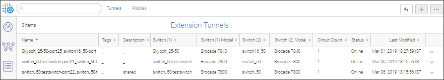
The different configuration status values are defined below.
Configuration Status | Description |
|---|---|
ONLINE (Online) | Both ends of the tunnel have status of ONLINE. |
OFFLINE (In Progress) | If either end of the tunnel is not ONLINE, then the tunnel status is OFFLINE. |
INACTIVE | The tunnel configuration is not pushed to the switch. |
DEGRADED | One switch is DEGRADED and the other is either ONLINE or DEGRADED. |
DISABLED | If either end of the tunnel is DISABLED, then the tunnel status is DISABLED. |
Note: One-sides tunnels (discovered from a switch) are not displayed in the Extension Tunnel configuration list. You can only see those tunnels from Inventory connections.
Note: If the list of tunnels is incomplete, the SANnav server has yet to discover all the switches.
The description from the first switch is displayed. If the description is unavailable for first switch, then data from second one is displayed. If the description is set on the server but not set on either switch, the setting on the server is displayed.
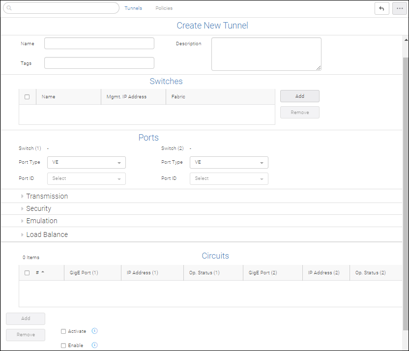
2. Click the + icon in the upper right corner of the Extension Tunnels page to create a new tunnel.
Once a name has been specified, it can only be changed through tunnel management configuration.
If switch (1) is FCR supported and both switch (1) and switch (2) belong to different FIDs, the default value for switch (1) is VEX and the drop down lists VEX before VE whereas switch (2) lists VE before VEX.
If you change the Port ID for one or both ports in the existing tunnel configuration, the complete tunnel configuration is recreated.
3. Enter a tunnel name, a description and optionally, tags. The tunnel name must be at most 512 characters (the description can be at most 512 characters ) and valid characters include numbers, alphanumerics, and underscores.
4. Click the Add button to select switches for each end of the tunnel.
The Add Switches dialog displays.
Note: The Add button is disabled if there are already two switches in the list.
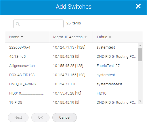
5. Select two switches from the listing, one for each end of the tunnel, and then click OK.
6. Scroll down to the Ports component of the Create New Tunnel page, and then select the port type and ID for the ports used at each end of the tunnel.
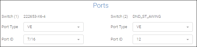
Note: For the Brocade 7840 Switch and the Brocade SX6 Blade, only the VE port type is applicable.
The Port ID selects the virtual ports configured in the selected switch.
7. Scroll down the page to configure additional tunnel properties.
◦ To assign Transmission-related properties, click Transmission.
These properties (compression modes, QoS distribution, and IP Extension configurations) are specific to the switch and tunnel type.
This is a sample Transmission dialog for a FCIP tunnel on a Brocade 7840 Switch or Brocade SX6 Blade.
By default, the configured tunnel is enabled to run FCIP mode. However, if you want to enable the configured tunnel in Hybrid mode (thereby running both FC and IP traffic) you must check Enable IP Extension Mode, as in the following sample Transmission dialog.
Note: To enable IP Extension mode, hybrid mode must be enabled on the switch.
Note: IP Extension mode is not supported on the Brocade FX8-24 Blade.
Select the desired IP Compression Mode. The default is "Off."
◦ To assign IP Security policies to a tunnel that is already configured within the switch, click Security.
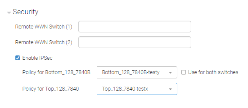
The fields Remote WWN Switch (1) and Remote WWN Switch (2) ensure that both switches have known World Wide Names.
If you intend to use the same IPsec policy for both switches, check Use for both switches.
For example, if you wanted to use the same IPSec (PSK) policy on both switches, you would do one of the following.
▪ As you configure a tunnel, set the IPsec policy:
1. Enable IPsec.
2. Select the configured IPsec policy from the configured switch.
3. Check Use for both switches.
4. Save the configuration.
▪ Configure a tunnel with IPsec-enabled (PKI):
1. Configure an IPSec policy on a switch and its peer.
2. During tunnel configuration, enable IPsec.
3. Choose the configured IPsec policy name for both switches.
4. Save the configuration.
◦ To configure Fast Write, click Emulation.
Default values are populated if you check FICON.
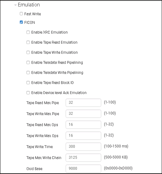
Note: Although values within the range 0x0000 to 0xF000 are valid for Oxid Base, to avoid conflicts you should choose a value outside the range used by FICON channels and devices.
◦ To load balance your circuits in the event of failover or spillover, click Load Balance.
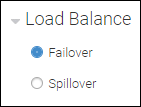
Note: The Spillover option is supported only the Brocade 7840 Switch or Brocade SX6 Blade, provided the firmware on both switches is v8.0.1 or above.
8. To add circuits, scroll down the Create New Tunnel page, and then click the Add button.
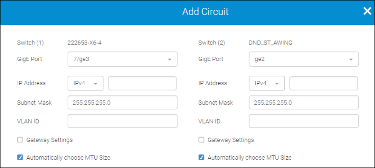
Although you can choose either IPv4 or IPv6 address type based on the interface requirements, your selection of Address type must match for both switches. Similarly, the VLAN ID, which can range from 1 thru 4096, must be the same for both interfaces.
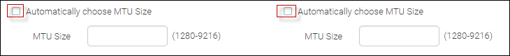
By default, the system automatically selects the MTU size. If you uncheck this option, you must manually specify an MTU size for the IP interface within these parameters: 1280 thru 9216 (for 7840 and SX6) and 1260 thru 1500 (for FX8-24).
On the lower half of the Add Circuit dialog, you can set circuit values to maximize the effectiveness of the extension tunnels.
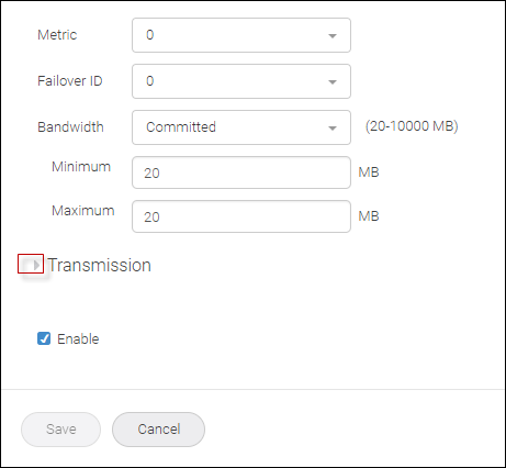
Metric identifies the failover circuit. Typically, all circuits within a given tunnel utilize the same Metric ID number. If you want some circuits to function solely as failover circuits, assign them all the next higher Metric ID number.
If the circuit transmission fails, SANnav attempts to re-send the transmission through the same Metric ID. If that fails, SANnav re-transmits through the next Metric ID. For example, only after all circuits with Metric ID number 0 fail will circuits with Metric ID number 1 be used.
If you click Transmission, you can set transmission properties.
For Keep Alive Time Out, the default values are 6000 ms (for the Brocade 7840 Switch and the Brocade SX6 Blade) and 10000 ms (for the Brocade FX8-24 Blade).
9. At the bottom of the Create New Tunnel page, you determine the activation and status of the tunnel.
Hovering over each i (information) icon, displays details for that option.
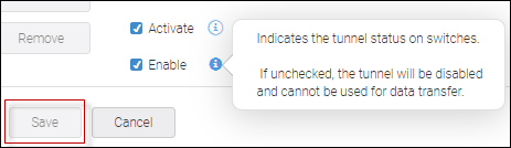
The following scenarios describe the interaction between the checkboxes and the Save button.
◦ If you uncheck Enable, check Activate, and click Save, the tunnel is deployed to the switch but is in a disabled state.
◦ If you check Enable (Activate is thereby checked automatically) and click Save, the tunnel is deployed to the switch in an online state.
◦ If you uncheck Enable, uncheck Activate, and click Save, the tunnel is saved to the SANnav database but not deployed to the switch.
Parent topic